-40%
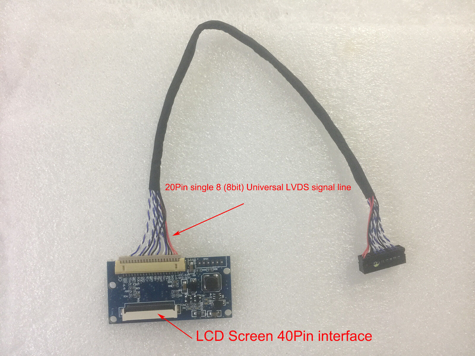
LVDS 20Pin to 40Pin Conversion driver board For 7-8 inch 40Pin LCD screen panel
$ 6.33
- Description
- Size Guide
Description
View more great itemsProduct Details:
- The driver board is a LVDS signal input, LVDS signal through output, and integrated LED backlight driver, and can produce AVDD, VGL, VGH, VCOM, and other multi-voltage LCD adapter board.
- The driver board can support EJ070NA-01J, EJ080NA-04B, EJ080NA-04C, EJ101NA-01, etc., universal 40PIN LCD screen, or function and define the same LCD screen.
- The drive board, LVDS signal input using the standard DF14-20P interface, and the interface definition using a common single 8 (8bit) general LVDS signal line.
- The driver board defaults to 8BIT standard LVDS signal input, can not support 6BIT signal input, please note.
Feature Description:
Input signal
LVDS
Support mode
8BIT (Default)
Interface
Standard LVDS signal interface DF14-20P
LCD screen signal interface
40PIN-0.5MM Standard EJ080NA-04C definition
Inverter interface
6PIN standard socket (Not installed by default)
Input voltage
With the screen power supply 3.3V (No need to set it separately)
special
Support LED backlight driver
Interface function details:
-
Inverter 6PIN interface
(
This interface, the default is not installed need to adjust, please refer to the following technical adjustment instructions
)
Serial number
Definition
Description
1
+5V
Positive power input
2
+5V
Positive power input
3
EN
High pressure plate Switch signal
4
5
GND
Ground
6
GND
Ground
20Pin LVDS signal interface:
Serial number
Definition
Description
1
VCC
LCD screen power supply
2
VCC
LCD screen power supply
3
GND
Ground
4
GND
Ground
5
LAX0-
Ground
6
LAX0+
Ground
7
GND
LVDS signal
8
LAX1-
LVDS signal
9
LAX1+
LVDS signal
10
GND
LVDS signal
11
LAX2-
LVDS signal
12
LAX2+
LVDS signal
13
GND
14
LACK-
15
LACK+
LVDS signal
16
GND
LVDS signal
17
LAX3-
LVDS signal
18
LAX3+
LVDS signal
19
GND
GND
20
Set 6bit / 8bit
If you need to adjust, please refer to the following technical settings (default is 8BIT)
40Pin LCD screen interface Pin Assignment
Pin
No.
Symbol
I/O
Function
Remark
1
VCOM
P
Common
Voltage
2
VDD
P
Power
Voltage
for digital
circuit
3
VDD
P
Power
Voltage
for digital
circuit
4
NC
---
No
connection
5
Reset
I
Global reset
pin
6
STBYB
I
Standby
mode, Normally pulled high STBYB = “1”, normal operation STBYB
=
“0”,
timing
controller,
source driver will turn off, all output are
High-Z
7
GND
P
Ground
8
RXIN0-
I
-
l
V
D
S
d
i
f
f
e
r
e
n
t
i
al
d
a
t
a
i
nput
9
RXIN0+
I
+
l
V
D
S
d
i
f
f
e
r
e
n
t
i
al
d
a
t
a
i
n
p
u
t
10
GND
P
Ground
11
RXIN1-
I
-
l
V
D
S
d
i
f
fe
r
e
nt
i
al
d
a
t
a
i
nput
12
RXIN1+
I
+
l
V
D
S
d
i
f
f
e
r
e
n
t
i
al
d
a
t
a
i
n
p
u
t
13
GND
P
Ground
14
RXIN2-
I
-
l
V
D
S
d
i
f
f
e
r
e
n
t
i
al
d
a
t
a
i
nput
15
RXIN2+
I
+
l
V
D
S
d
i
f
f
e
r
e
n
t
i
al
d
a
t
a
i
n
p
u
t
16
GND
P
Ground
17
R
X
C
l
KI
N
-
I
-
l
V
D
S
d
i
f
fe
r
e
nt
i
al
c
l
o
c
k
i
nput
18
R
X
C
l
KI
N
+
I
+
l
V
D
S
d
i
f
fe
r
e
n
t
i
al
c
l
o
ck
i
nput
19
GND
P
Ground
20
RXIN3-
I
-
l
V
D
S
d
i
f
f
e
r
e
n
t
i
al
d
a
t
a
i
nput
21
RXIN3+
I
+
l
V
D
S
d
i
f
f
e
r
e
n
t
i
al
d
a
t
a
i
n
p
u
t
22
GND
P
Ground
23
NC
---
No
connection
24
NC
---
No
connection
25
GND
P
Ground
26
NC
---
No
connection
27
DIMO
O
Backlight CABC controller signal
output
28
SElB
I
6bit/8bit mode
select
Note1
29
AVDD
P
Power for Analog
Circuit
30
GND
P
Ground
31
lED-
P
l
ED
C
at
h
o
d
e
32
lED-
P
l
ED
C
at
h
o
d
e
33
l/R
I
Horizontal
inversion
Note3
34
U/D
I
Vertical
inversion
Note3
35
VGl
P
Gate OFF
Voltage
36
CABCEN1
I
CABC H/W
enable
Note2
37
CABCEN0
I
CABC H/W
enable
Note2
38
VGH
P
Gate ON
Voltage
39
lED+
P
l
ED
A
n
o
de
40
lED+
P
l
ED
A
n
o
de
I
: input,
O
: output,
P
: Power
- Note1: If lVDS input data is 6 bits ,SElB must be set to High;
- If lVDS input data is 8 bits ,SElB must be set to low.
- Note2: When CABC_EN=”00”, CABC OFF.
- When CABC_EN=”01”, user interface image. When CABC_EN=”10”, still picture.
- When CABC_EN=”11”, moving image.
- When CABC off, don t connect DIMO, else connect it to backlight.
- Note3: When l/R=”0”, set right to left scan direction.
- When l/R=”1”, set left to right scan direction. When U/D=”0”, set top to bottom scan direction. When U/D=”1”, set bottom to top scan direction.
When installing the drive board technology function, please read the following instructions carefully, and pay attention to the correct operation in the technical improvement, so as not to damage the drive board or LCD screen.
6BIT-8BIT signal input setting
:
Control principle, this setting is to control the LCD screen 28PIN, the high and low levels to complete the signal input recognition settings, because the drive board to set the resistance, so no separate wiring.
LVDS signal input type
R29
R32
Remarks
6BIT
NC
0R
Need to be improved as required
8BIT
0R
NC
This driver defaults to this state,
The settings for the backlight input and switch control sections:
The driver board defaults a LVDS signal line input, and in the LCD screen power supply 3.3V, take LED backlight power supply and switch control signal.
When the LCD screen needs a larger current, or in the use of high brightness LCD screen, did not reach the normal brightness, you can follow the following improvements.
Backlight power supply type
R33
R36
6PIN
Remarks
3.3V
10R(
magnetic bead)
10K
(resistance)
NC
When the default state
5V
NC
NC
Install 6PIN-2.0 row seats
Need to improve the technology, but be sure to remove the two bits on the components and then connected to the power, otherwise it may damage the LCD screen and related circuit boards.
Backlight power supply shall not be greater than 6V, otherwise it may damage the backlight driver IC, or LCD screen.
Backlight switch signal, not more than 5V, otherwise it may damage the backlight driver IC.
- 100% test before sending.
- If you need to receive your item quickly, please select
Expedited International Shipping
and you will be charged an additional shipping fee. We will send items via
DHL
or
other courier
.
(
Brazil
and
Russian Federation
cannot be transported via DHL and any other commercial express delivery, please note.)
-
Russian Federation
customers please leave your Full name and Full Address zip code information.
- If you’re not sure if it’s the right item you need, Please contact me before ordering.
- If you need more quantities, please contact me via eBay Messages before purchasing.
Packing include:
- LVDS 20pin to 40pin Conversion board x
1
- LVDS 20-pin single 8(8-bit) cable x
1
Shipment:
- The items you ordered will be shipped out in 1~3 business days after your payment is completed.
- We will send the item to buyer's address provided by your eBay account, if you want the item to be sent to different address, please specify by eBay message to confirm before placing order.
- Please make sure the postal address is correct, we will not be liable for postal lost caused by incorrect & invalid address provided.
- We offer combined shipping, but no local pick-up service.
-
NOTICE:
Import duties, taxes and charges are not included in the item price or shipping charges.
- Please check with your country’s customs office to determine what these additional costs will be prior to bidding / buying.
-
We only accept
PAYPAL
payments.
- All payments are expected within 7 days after the auction is closed. All non-pay bidders will be reported to eBay and get an unpaid warning from e-Bay.
- Combined Shipping for multiple items is available upon request. We offer discount on the Shipping & Handling Charge for any additional item being sent to the same address. The more you buy, the more you save.
Returns:
- We do our best to serve our customers the best that we can.
- If the items are defective, please contact us via eBay Messages within 30 business days after receiving the item.
- If it is proved to be a wrong item or have a manufacturer defect, please send back the item and we will send you an replacement for free.
- The returned item and all accessories must be in the original (unused) condition,Each item is pasted with a warranty label, please do not tear up the label.
- If the items are damaged or lost when they are returned, the buyer will be responsible for such damage or loss, and we will not give the buyer a full refund. The buyer should try to file a claim with the logistic company to recover the cost of damage or loss.
- The buyer will be responsible for the shipping fees to return the items.
Feedback:
- If you are satisfied with my project, please give me a positive feedback, as this will encourage me to serve more people around the world around the world.
- If you are not satisfied with my item,please contact me via eBay Messages.Due to time zone difference, messages will be replied within 24~48 hours.
- Negative feedback won’t make a pleasant transaction,let’s figure out a solution together to make a good seller and a happy buyer.
Contact Us:
- If you haven't received your goods over 45days(Except Christmas and New year day). Please contact us via eBay Messages.
- We do not want to give our customers a bad buying experience, even the delivery is not what we can control.
- Your satisfaction and positive feedback will be highly appreciated. Please do not be quick to leave negative/neutral feedback. Any problem we will try our best solve it.
- We care about our valued customers and will do our best to help you. So if you have any questions, please contact me immediately.
- Thank you for your support. Happy shopping!
